Powertrain, Intake and Chassis for Formula Student

Formula Student is a competition held every year in multiple locations around the world where students from various universities race their cars against each other in different events. There are a range of different static and dynamic events which aim to test the design, the manufacturing and the reliability of each car as well as the administrative operation of each team.
I had the opportunity to take part in this project which counted as the coursework element of the new Automotive Design and Motorsports (ADM) module offered at my university.
The project consisted of producing the theoretical design, manufacturing plan and engineering drawings for two systems present in a formula student car. As such, we had to constrain our innovative ideas to the regulations provided by Formula Student UK.
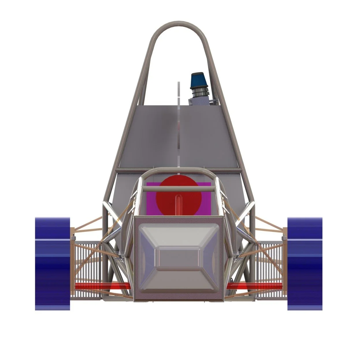
I was part of a team of six student engineers who chose our two systems to be the powertrain and the chassis of the car. Careful planning within the team resulted in me being responsible for the design of the intake components of the power unit. Other components within the powertrain system that were developed by other members of the team include the exhaust, selection of the engine and transmission components. Similarly, iterative design and computational methods were used to progressively design a chassis that would provide appropriate mounting points for all other components as well as safely accommodate the driver.
Due to the very wide scope of this project, which needed to be completed within three months (one academic term), the team took a pragmatic approach where the priority was to develop reliable components that would do their job correctly. The initial stage of the project involved an extensive literature review to determine which ideas and design methodologies would often lead to successful results.
Intake System
For the intake system, I decided to gather inspiration from different technologies often found in road vehicles. The use of forced induction was investigated but I ultimately decided that natural aspiration of the internal combustion engine would strike a better balance between design complexity, cost, performance and ease of manufacture.
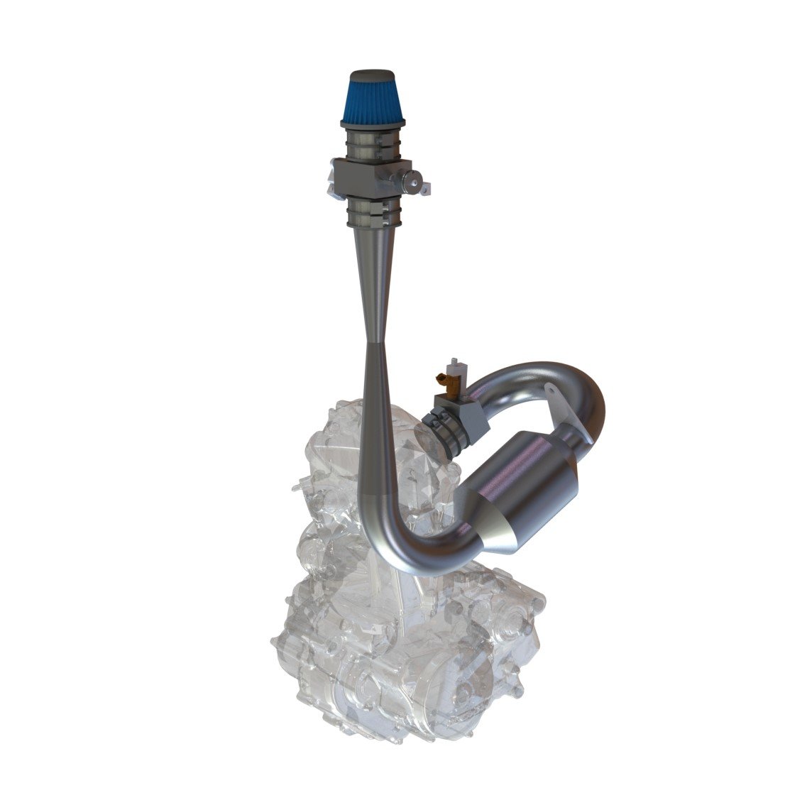
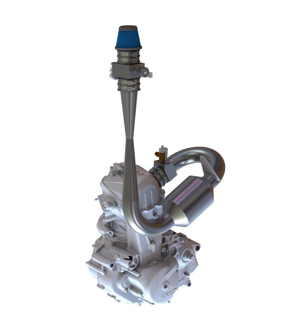
The main components of the intake system included the air filter, the throttle body, a flow restrictor required by the regulations, the plenum and the intake manifold.
In this case, since the engine selected by the team was a single cylinder KTM 690 Duke motorbike engine, the intake manifold consisted of a single runner. The phenomenon of air pulses being generated inside the intake system due to the opening and closing of the intake valves was used to determine the dimensions of this intake runner. The length of this component was selected such that a reflected wave of air would arrive at the intake valve just when it begins to open. The effect of this is that air would be rammed into the cylinder, increasing the volumetric efficiency of the engine at a given speed. These dimensions were tuned for the maximum power operating point of the engine. Computational methods were also used to determine the dimensions of the plenum and the flow restrictor that would result in minimal pressure drops across the intake system. A custom-made throttle body was also designed to fully comply with the Formula Student regulations.